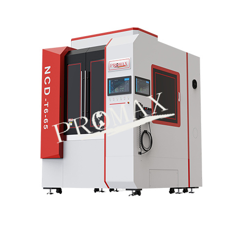
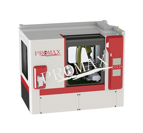
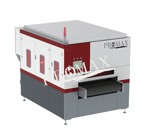
■ Product features:
● 6-Axis Simultaneous Machining: Cradle swings ±110° with 360° rotation on the C-axis; tool swings ±180°.
● Rotating Cutter Head: Equipped with six electric spindles (4.5–7.5 kW) operating at 40,000 RPM, eliminating tool change time to enhance efficiency.
● Advanced CNC System: Utilizes Yaskawa and custom intelligent polishing system with 125 ms communication cycle for high-speed, high-precision motion control.
● Tooling Options: Includes floating tools, rigid tools, soft tools, and polishing tools.
● Continuous Cooling: Gas-liquid cooling for the power head tool, avoiding the need for tool reset.
● Pneumatic Clamping Fixture: Features dynamic avoidance and super-point clamping for secure workpiece handling.
● Optimized Design: Hollow fixture design with large cradle swing and continuous tool swing for seamless operation.
● Durability Features: Resistant to oil, corrosion, and dust with heat-treated, surface-treated materials for extended lifespan and stability.
■ Six-axis machine parameters
Serial number | Project name | Parameter item |
1 | Number of feed axes | 6 |
2 | Number of configuration tools | ≥4 |
3 | X axis travel | 650mm |
4 | Y axis travel | 550mm |
5 | Z axis travel | 320~450mm |
6 | A axis travel | ≥±120° |
7 | B axis travel | ≥±190° |
8 | C axis travel | ±360° |
9 | Maximum diameter of machinable parts | φ720mm |
10 | X axis repeatability | 0.03mm |
11 | Y axis repeatability | 0.03mm |
12 | Z axis repeatability | 0.03mm |
13 | A axis repeatability | (Arc min) <1 |
14 | B axis repeatability | (Arc set) ≤10 |
15 | C Axis repeatability | (Arc set) ≤10 |
16 | X axis maximum speed | 600mm/S |
17 | Y axis maximum speed | 600mm/S |
18 | Z axis maximum speed | 500mm/S |
19 | A axis maximum speed | 235°/s |
20 | B axis maximum speed | 205°/s |
21 | C axis maximum speed | 205°/s |
22 | Maximum composite speed | 980mm/S |
23 | Maximum load of worktable | 70kg |
24 | Single spindle power | 3.5kW~7.5kW |
25 | Number of electric spindles | ≥3 |
26 | Electric spindle speed | 100r~40000r/min |
27 | Handle diameter | φ3~φ16mm |
28 | Working voltage | AC380V |
29 | Rated power | ≥12kW |
30 | Machine size (length*width*height) | ≤1800*2100*2490mm³ |
■ Product advantages
6-Axis Simultaneous Machining: Ensures the deburring tool reaches any part of the workpiece at the required angle for thorough polishing and cleaning.
Professional Deburring Expertise: Extensive range of deburring tools and processes tailored to user needs, ensuring optimal configuration and reduced consumable costs.
Tool Options:
Imported Floating Blade Head: Pneumatic floating blade head with long service life and adaptive blade size.
Standard Rigid Tools: Includes universal milling cutters, reamers, twist drills, and spherical cutters.
Standard Flexible Tools: Includes Ø3mm–Ø16mm round files, flat files, steel brushes, and ceramic fiber brushes.
Polishing and Grinding Tools: Includes flexible options such as flap wheels, grinding wheels, cloth wheels, and steel wire wheels.
Optimized Tool Trajectory: Allows intuitive configuration with optional teaching programming features.
Compact Design: Integrated functions, space-efficient layout, and a small footprint.
User-Friendly: Ergonomic, easy to operate, maintain, and clean, with robust protection and environmental considerations.
Application Case: Cylinder Block Deburring
Purpose: Cleans burrs on six surfaces of cylinder blanks, reducing manual inspection and cleaning workload.
Workpiece Dimensions: 420 × 400 × 230 mm with marked cleaning areas.
■ Application Cases
Cylinder block case
1. Equipment purpose: Used for cleaning burrs and burrs in designated areas on six surfaces of cylinder blanks, reducing manual inspection and cleaning workload.
2. The schematic diagram of the deburring position of the cylinder blank is shown below (for reference only). The dimensions of the cylinder blank (420 * 400 * 230) and the cleaning area are marked in red.

3. The burr cleaning equipment is planned to be installed in the lower sequence of the die-casting machine. The original layout of the die-casting machine is shown in the figure (the picture is for reference only). The related accessories of the deburring equipment, such as the water cooling device, tool wall, fixture, positioning device, etc., are all within the range of the robot's motion radius, and should be arranged in a way that saves time. The layout of the newly added burr cleaning equipment is shown in the figure.
Serial Number |
Logistics process of cylinder block before renovation |
Logistics process of modified cylinder body |
1 |
The pick-up robot retrieves the cylinder body from the die-casting machine |
2 |
Integrity inspection of the cylinder body clamped by the pickup robot at the entrance of the air-cooled roller conveyor |
3 |
The picking robot places the cylinder body on the sawing machine for sawing the material cake |
4 |
The picking robot takes pieces from the sawing machine to the trimming machine for trimming |
5 |
The picking robot retrieves the cylinder body from the trimming machine and places it on the automatic coding table for coding |
The picking robot takes out the cylinder body from the trimming machine and places it in the water cooling device lifting mechanism for cooling |
6 |
The automatic coding table completes the coding and places the cylinder body on the air-cooled roller conveyor through the lifting and horizontal movement mechanism. |
The lifting mechanism of the water cooling device sinks into the water to cool the cylinder body to the specified temperature |
7 |
The cylinder body is transported to the manual cleaning platform through an air-cooled roller conveyor |
The lifting mechanism of the water cooling device rises, and the burr unit robot clamps the cylinder body from the water cooling device for local cleaning, and sends it to the CNC |
8 |
Manually inspect and clean the cylinder body |
The burr unit robot retrieves the cylinder body from the CNC and clamps it for laser coding. |
9 |
Manually place the cylinder body on the logistics roller conveyor and flow it into the next sequence |
Burr unit robot clamps cylinder body and places it on air-cooled roller conveyor |
10 |
The cylinder body is transported to the manual cleaning platform through an air-cooled roller conveyor |
|
11 |
Manually inspect the cylinder body |
|
12 |
Manually place the cylinder body on the logistics roller conveyor and flow it into the next sequence |
Schematic diagram of the original layout of the die-casting machine (the picture is for reference only)
Schematic diagram of the installation of the deburring equipment of the die-casting machine (the picture is for reference only)
Front view of the shell and summary of total polishing time for the product
Use D16X150 upright milling cutter to treat burrs, taking 6 seconds
Use a copper ball ball cone milling cutter to process the mold line, with a processing time of approximately 5 seconds
Use a coated steel brush to remove burrs from the top pin position, which will take 10 seconds
Use a file to remove burrs, which takes 5 seconds
Use R4XD10XL150 ball end taper milling cutter to treat burrs, which takes 56 seconds
Diagram of the reverse side of the shell and summary of the total polishing time for the product
Use D16X150 upright milling cutter to process burrs, with a processing time of approximately 12 seconds
Use a copper ball ball cone milling cutter to treat burrs, which takes 42 seconds
Use a floating file to remove burrs, which takes 11 seconds
Use a coated steel brush to handle the top pin position, which takes 27 seconds
Keywords: Six axis deburring machine

Six axis deburring machine
Classification